Bistatic passive radar with an RTLSDR
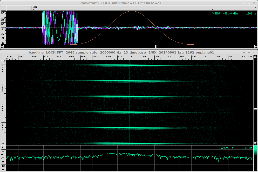
In the video above, recorded from baudline, I am receiving the direct and reflected pulses from an L-band radar on Učka, Croatia - a Lockheed Martin AN/FPS-117 at the time of the recording (summer 2014). The receiver was 83 km away, with clear LOS to the radar site (N45.2868, E014.2027, Street View).
The center frequency of the pulse-compressed blip is 1258 MHz, which at the time seemed to be one of the four frequency the radar was transmitting on. The receiver is a RTL-SDR dongle bought in 2013 (on which you can read more about here), with a R820T tuner IC, connected to a 2-dipole collinear array (tuned for 403 MHz) with approx. 7 m of Belden 1694A RG-6 coax.
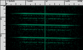
The output of the command line tool rtl_sdr was piped to baudline (following the useful information by DM5MS). The IQ sampling rate is 2 MHz; the transform is a complex STFT (size is 2048 samples, Blackman window). The video shows a 0.008x speed playback of 15 ms of actual recording. The reflected pulses become more time-local when using a shorter transform window size, as expected, e.g. 512 samples:
The waveform seems a rather nice example of pulse compression in action:
The video was recorded from screen with VLC, the audio piped to stdout and saved, then audio and video were synced in Blender.
A detection attempt
The direct-reflected delay of the event shown in the video is approx 278 µs, which would be compatible with a receiver-to-target distance of 42 km, in a simple 2D along-beam normal incidence model. In other words: assuming that the target lies on the extension of the line that connects the radar to the receiver. If we allow for the target to be slightly off beam, the geometry of the problem becomes less dull:
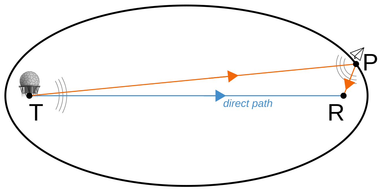
In the sketch above (author: myself, license: CC0), we can see that the locus of reflectors satisfying the delay along the transmitter-plane-receiver T-P-R path (with respect to the T-R direct path) is an ellipse, provided that the three points lie on a plane - since they do not, the solution becomes an ellipsoid. The trivial derivation is left as an exercise.
Let’s keep in mind that this off-angle cannot be extremely large: it is limited by the transmitter antenna beamwidth - unless the receiver is so close to the transmitting radar that all the transmitted pulses, even when the dish is pointing elsewhere, are above its noise floor (out of experience: it works). Interestingly, also the backscatter of the target from these unusual aspects comes into the model, something that is exploited in other context, unsurprisingly.
There’s another fainter echo closer to the pulse - it may be another target or a time-sidelobe of the main pulse (a side effect of pulse compression?). Anyway, I must state that I have no formal knowledge on these topics. So you’d better take all this with a grain of salt ;) and go check it on a more reputable source.
I am quite happy to see this was featured on the RTL-SDR.com blog on January 12, 2015 and mentioned sometime later on r/rtlsdr.
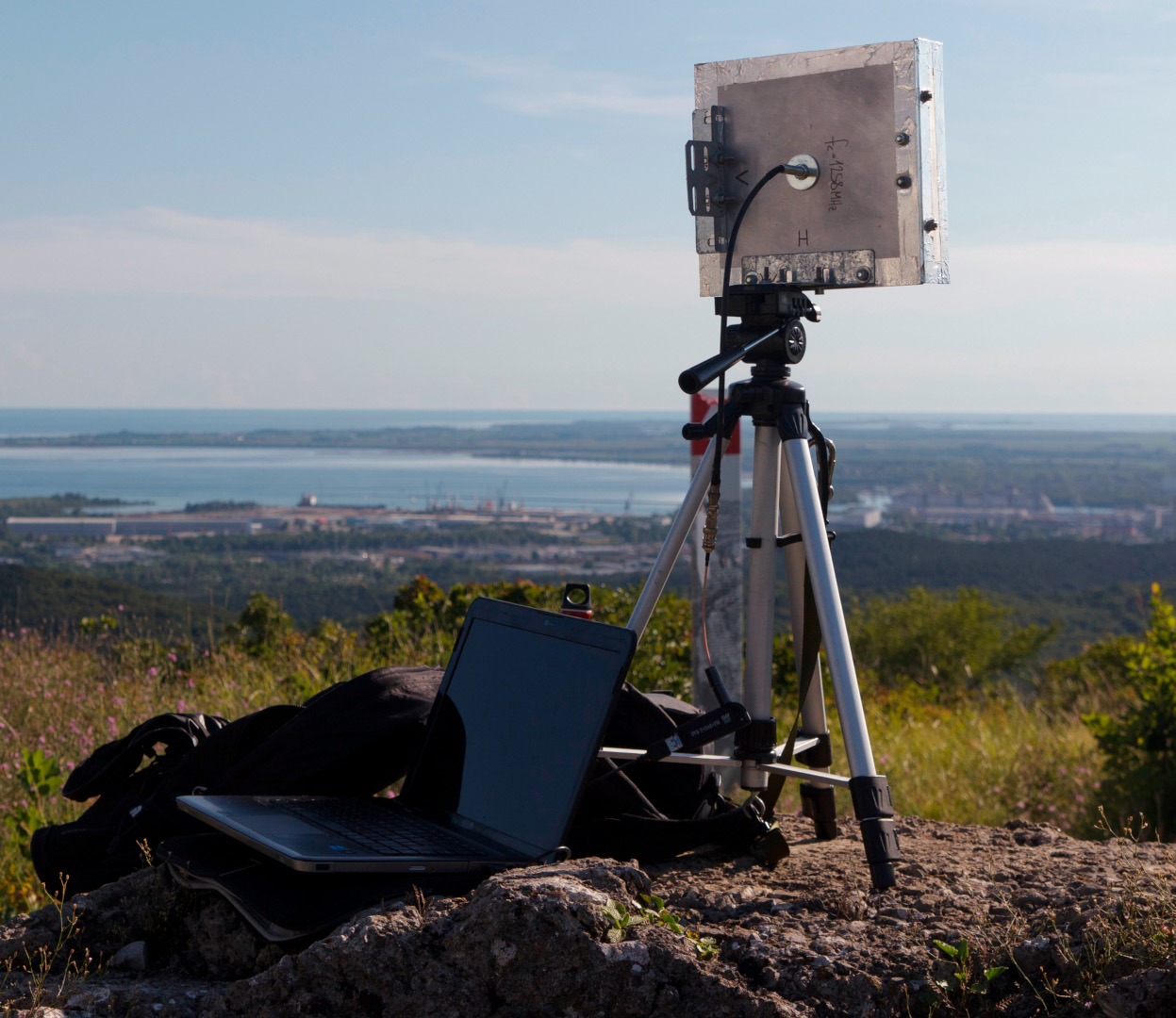
The image below shows a later attempt, with an L-band bi-quad antenna out in the field.
Further work
This has been a nice and fun experiment, however it needs hand picking of events and measuring delays. Also, it does not leverage the advantages of pulse compression in any way. It would be nice to try some processing on the received pulses (deconvoluting them with received direct pulse?), then to move on with automated detection. Alas, I feel that I do not have the knowledge nor the time to embark in such a project. Is anyone willing to?