A dull mistery: ethernet shorted over
Summary: a PoE powered IP camera stopped working and I have tried to figure out why. Spoiler: I get to no conclusions here, but ruling out the various options has been somewhat fun.
An IP camera that I had placed on the roof suddenly stopped working after more than four years of flawless operation. The day of the mishap was rather unremarkable: no heavy rain, not particularly warm not cold, no thunderstorms - surely not the worst day it had endured up there. For the sake of gratuitous pedantry, a Mean Time Between Failures (MTBF, sample size = 1) of 1544 days: 2018-09-20 to 2022-12-12.
I took for granted that among all the links in the chain, the IP camera was the failed one. In light of this, the solution entailed buying a new one and climbing on the roof to swap them - a rather cumbersome and a risky business even with all due precautions, which I would have been happy to avoid.
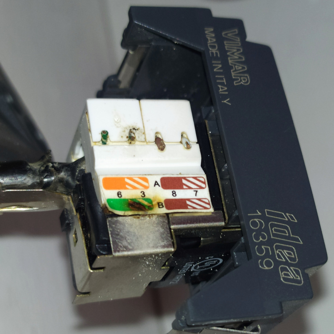
The somewhat disappointing surprise after this adventure was finding out that the even the new camera was not powering on. Suspecting some mistake with crimping the 8P8C jack on the roof under a blazing August sun, arguably not the most ideal place and time for such a task, I crimped a new one - to no avail. After a disappointing trip back down, the old camera was now working fine, on the bench. Thinning down the remaining options in this fun exercise in troubleshooting, I identified a likely culprit in the downstairs-end of the cable coming down from the roof: the Ethernet wall socket. Here it was, with a surprising stain:
Let’s get the wiring scheme sticker out of the way:
Striking signs of… arcing? can be seen between the wires in pair 3 (TIA/EIA 568B in use), the green and green-white wires, pins 6 and 3 in the 8P8C connector. That discoloration affected the label and the nearby shield - however UTP cable was used, so it was likely not part of the current path.
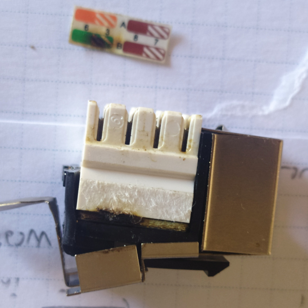
The socket is a Vimar Idea 16359 with an insert for CAT5e FTP, punchdown terminals. This insert is somewhat close to a Keystone insert, and loosely fits in one if one insists on trying (a rather dull finding). The cable is a CAT6 UTP direct burial cable, so there is a slight mismatch con wire gauge, on the larger side. Upon closer inspection, arcing seems to have happened on the small PCB on which the punchdown module and the actual 8P8C socket contacts are soldered on. The punchdown seems dirty, with a thin coat of something, while the rest of the wall box is remarkably clean. A corrugated tube, laid under mortar, connects the box to a J-shaped pole (which in Italy is aptly called a pastoral), following a rather common setup for a TV pole over here.
Given the setup, the pole shape in particular, there is no direct path for water from the roof to the socket box, albeit moisture might run trough it and condense. Was moisture enough to do this damage? Why there are no signs of water ingress in the box?
Maybe the answer should not be looked for in moisture, but in a phenomenon that rather thrives in the lack of it, instead. The failure happened on 2022-12-12, (maybe) a dry late-fall day. Could this be a static discharge, in which the pcb in the socket acted as a spark gap? (the spark gap with the lowest breakdown of everything involved?) However the two wires should be in a DC short both at the camera and in the PoE injector… to have a look into this, let’s dig a bit more in how PoE is implemented here. (for the sake of pedantry, we need to mention that a static discharge is not DC, which may matter)
The IP camera was powered through a Tenda 802.3af/802.3at PoE switch (TEG1105P, archive.org link), which still works fine.
It took a while to find its datasheet and relevant information: TEG1105P-4-63WDatasheet.pdf (archive.org link).
The PoE supply from the switch, which supports standard IEEE802.3at/af as an endspan device, on the pairs in this setup: “12+, 36- and 45+, 78-”.
This still leaves a question open, since the switch seems able to use either mode A or mode B (see e.g. the Wikipedia entry), and this is negotiated when the powered devices is connected.
If the arced over pair (36) is indeed the culprit, we may infer that mode A was negotiated. The connected webcam is 100BASE-TX capable, so it would make sense to allow wiring it with just 2-pair (pairs 2 and 3) CAT5 cable.
Still, an arc between the two wires in the same pair seems unlikely! They should be at the same potential: used together (in DC) for PoE and with a low impedance DC path between the two wires in the Ethernet transformers at each end, signalling being carried out differentially.
The switch also boasts a “6 kV lighting protection” and short-circuit protection. How is the isolation between the socket pins then? I have no insulation tester at hand, but a multimeter reads infinity between all the 8 pins except… 3 and 6, unsurprisingly! The 3-6 resistance is approximately 1.2 kOhm: not a dead short, however enough to render Ethernet signaling on that pair ineffective.
What happened between those two pins then? Maybe tearing the socket/pcb assembly apart and looking for other signs of damage between pairs would help - my bet is on arcing forming a faint carbon path between the affected traces. I am leaving this for a further chapter.